CSMFE
1 Introduction
It is well known that the strain and stress fields are discontinuous across the boundaries of elements in the classical finite element method (FEM). Shear locking and numerical instabilities, such as hourglassing, are commonly observed as a result of this deficiency when modeling near-incompressible solids or certain loading conditions. For example, it is known that in linear quadrilateral elements the deformations corresponding to bending modes of the element lead to zero strain energy. Bending modes in two adjacent quadrilateral elements resemble un hourglass and thus the name of hourglassing has been chosen for this type of instability. Enhanced strain fields that are incompatible with the displacement field has been applied in the past to address these issues. It has been shown that enhancing the strain field is not always efficient for resolving the shear locking and hourglassing problems. Furthermore, as already mentioned, the enhanced strain field is not compatible with the displacement field. This is where the compatible approaches become more attractive due to their efficiency and capability to address the problems mentioned above.
Compatible-Strain Mixed Finite Elements (CSMFEs) are a new class of elements that are developed based on the concepts in Exterior Calculus. In this class of elements, the same shape functions as in the classical finite elements are used to interpolate the displacement field; however, the displacement gradient and stress tensor are interpolated using vector valued shape functions that satisfy certain continuity conditions across the boundaries of elements. It has been shown that this approach leads to a formulation that does not suffer from the deficiencies attributed to the classical finite elements [1-3]. In the following sections, the properties of the shape functions used to interpolate the displacement gradient and stress tensor are briefly discussed.
2 Interpolating the Displacement Gradient
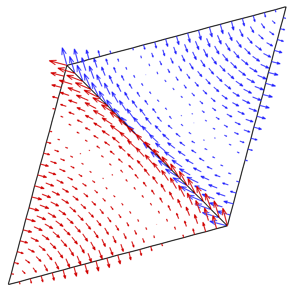
In order to discuss the shape functions that interpolate the displacement gradient, two adjacent simplex elements that share a common edge are considered. These simplex elements are shown in Figure 1. It can be shown that the shape functions that interpolate the displacement gradient are required to have a single-valued tangential component across an edge that is shared by two simplex elements [1-3]. Regarding Figure 1, it is observed that the tangential components of the shape function for the lower-left element (the variation of shape function is shown with red arrows) coincide with the tangential components of the shape function for the upper-right element (the variation of shape function is shown with blue arrows). It is interesting to note that the shape functions are normal to the edges that are not shared by these two simplex elements.
3 Interpolating the Stress Tensor
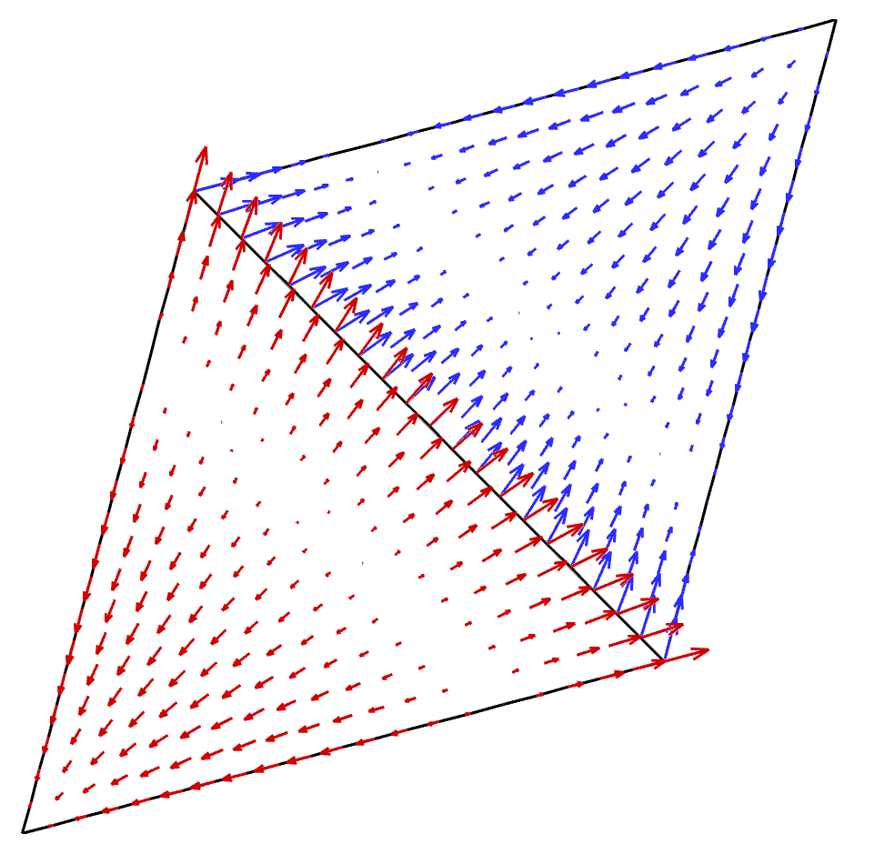
The shape functions that interpolate the stress tensor are required to satisfy the condition that the normal components of shape functions across an edge that is shared by two simplex elements should be single-valued [1-3]. Figure 2 presents the variation of shape functions over two adjacent simplex elements. It is observed that the normal component of the shape function for the lower-left element (the variation of shape function is shown with red arrows) coincides with the normal component of the shape function for the upper-right element (the variation of shape function is shown with blue arrows). Furthermore, it is noted that the shape functions are tangent to the edges that are not shared by the two simplex elements.
4 Examples
In this section, we present a few examples that demonstrate the application of compatible-strain mixed finite elements for modeling the behavior of near-incompressible solids. Through these and several other numerical examples it has been shown that the compatible-strain mixed finite elements do not suffer from the deficiencies attributed to the classical finite elements and thus they can be considered as an alternative for modeling complex behavior in solids [1-3]. The major problem with these types of elements is, however, the higher number of degrees of freedom for a given element that demands greater computational resources to be used for simulating a comparable finite element model.
4.1 Inhomogeneous Compressible Test
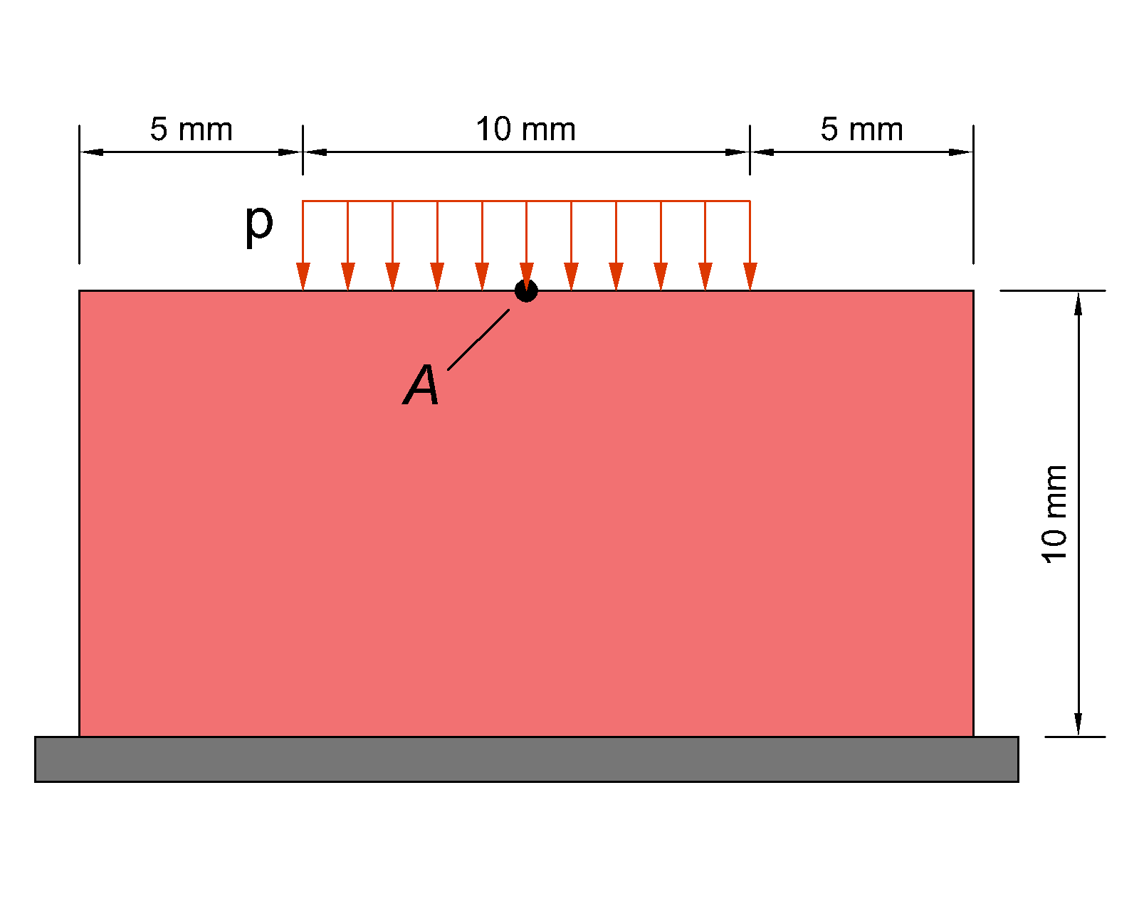
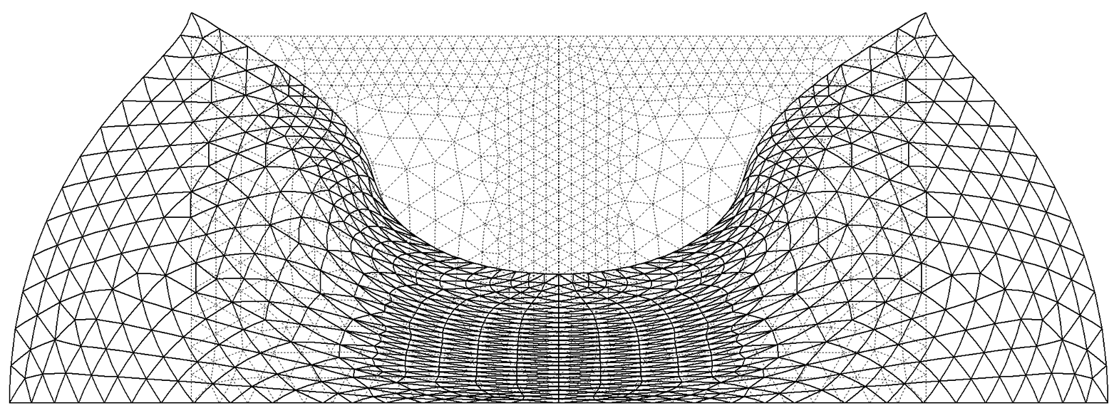
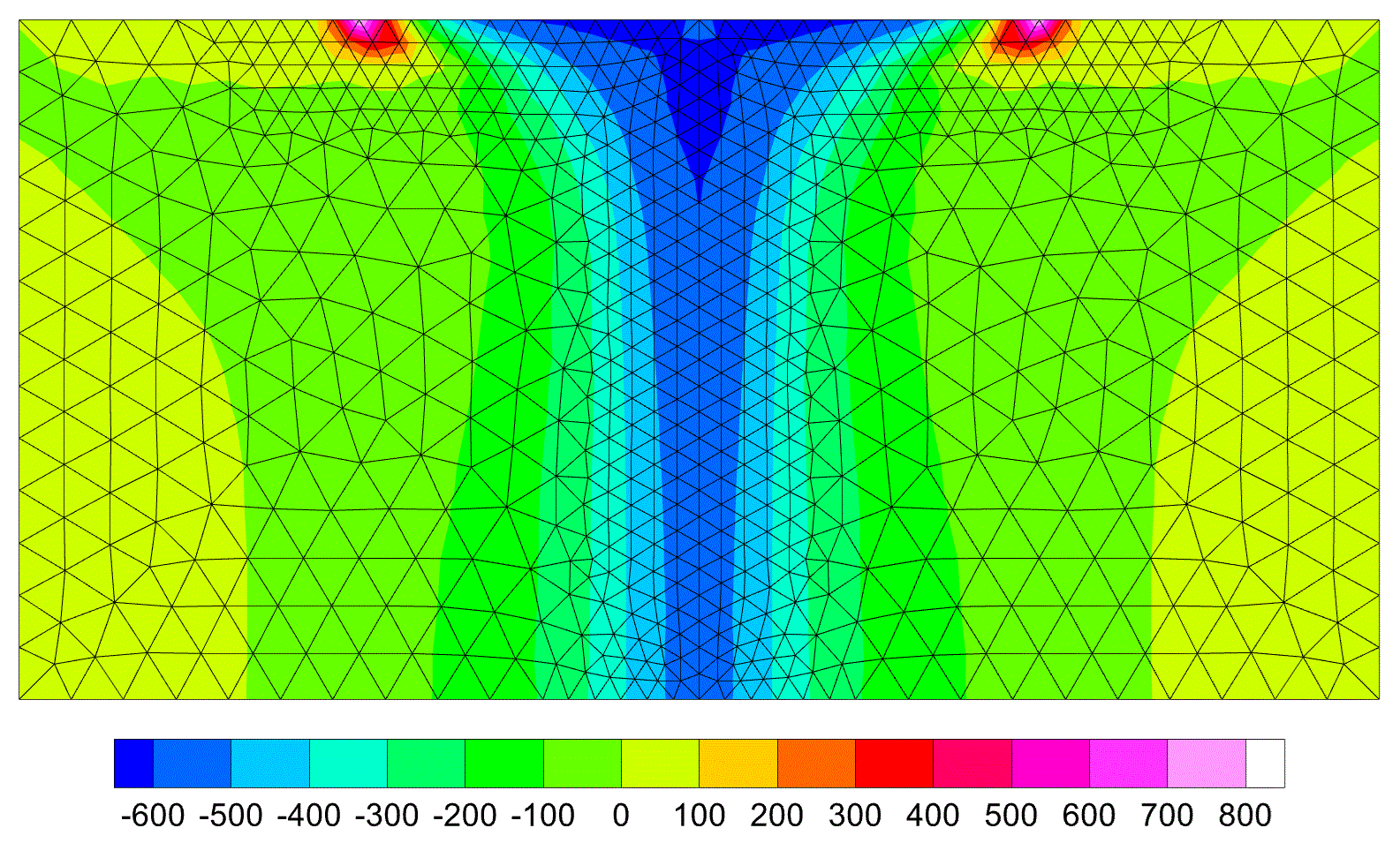
This example has been originally used to study the behavior of the first-order elements in connection with the hourglass instability [4]. The geometry and boundary conditions are shown in Figure 3. The bottom and top edges are restrained in vertical and horizontal directions, respectively. Due to symmetry, only half of the specimen is modeled. The material parameters μ = 80.194 MPa and κ = 400,889.8 MPa (κ / μ = 4999) are used for simulations. The value of the applied pressure is increased to p = 600 MPa, while the displacement of point A is monitored for different values of the pressure p. A very refined mesh of a second-order triangular element with U/P mixed formulation is required to obtain a target displacement of 6.491 mm for point A, while even coarse meshes of the second-order compatible-strain mixed finite elements are capable of computing this value of displacement. The deformed configuration corresponding to a mesh of 714 CSMFEs (for half of the specimen) and the contour of the Kirchhoff stress component τ22 for this mesh are shown in Figures 4 and 5, respectively.
4.2 Rubber Sealing Problem
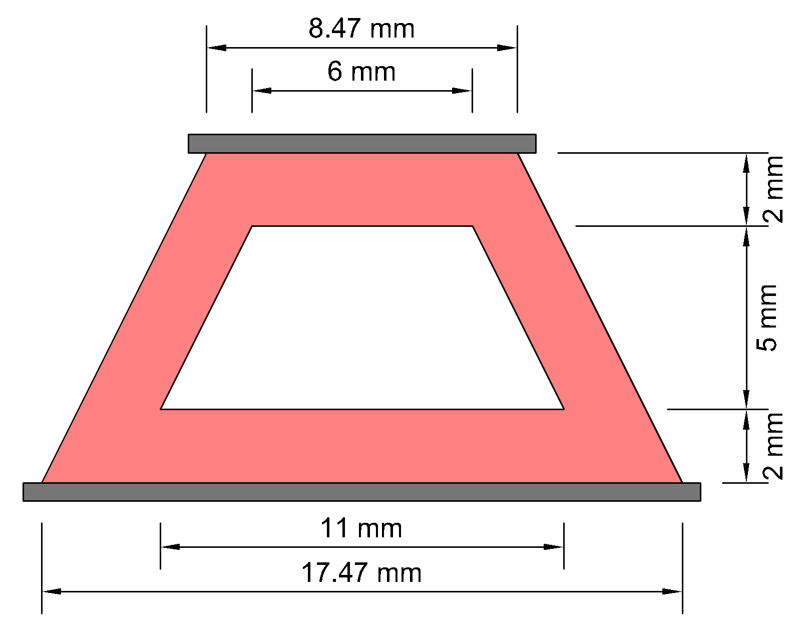
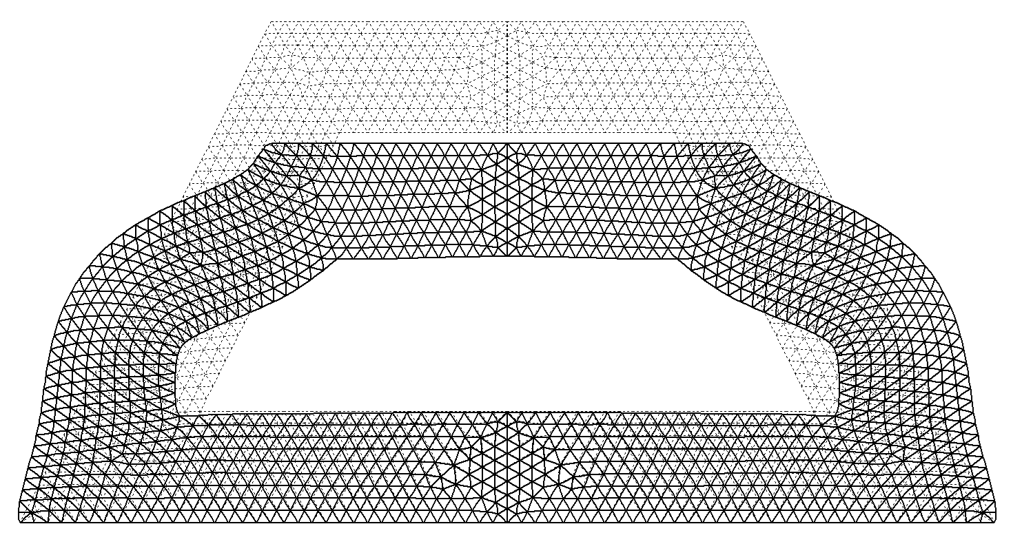
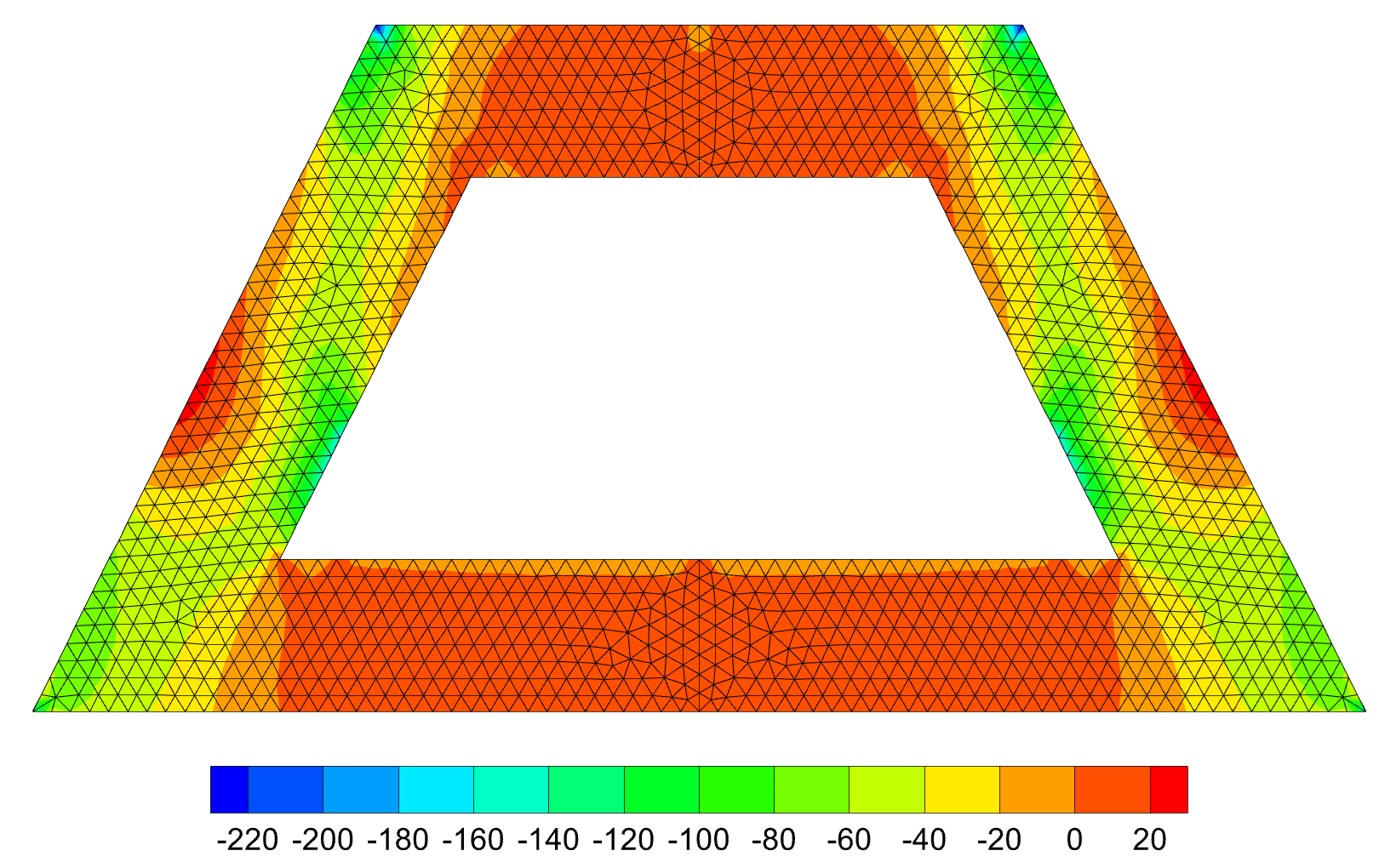
This problem was studied in [5] to provide a posteriori error estimate for finite element computations in finite elasticity. It involves the compression of a rubber sealing whose geometry and boundary conditions are shown in Figure 6. The top and bottom edges are restrained in the horizontal direction and the top edge undergoes an applied compressive deformation. The material parameters μ = 80.194 MPa and κ = 400,889.8 MPa are considered for simulations. The Q2/P1 element was used in [5] and the applied deformation was limited to 2.0 mm. It is noteworthy to mention that the maximum displacement that can be applied to the specimen using a mixed U/P formulation is 2.07 mm. On the other hand, it is possible to apply a maximum displacement of 2.2 mm using various meshes of CSMFEs. Figure 7 presents the deformed configuration for a mesh of 1326 CSMFEs (for half of the specimen) and the contour of the Kirchhoff stress component τ22 is shown in Figure 8.
References
- M. Jahanshahi, D. Pasini, and A. Yavari. Second-order compatible-strain mixed finite elements for 2D compressible nonlinear elasticity. Finite Element in Analysis and Design, 249:104369, 2025.
- M. Jahanshahi. A compatible mixed finite element method for large deformation analysis of two-dimensional compressible solids in spatial configuration. International Journal for Numerical Methods in Engineering, 123:3530-3566, 2022.
- A. Angoshtari, M.F. Shojaei, and A. Yavari. Compatible-strain mixed finite element methods for 2d compressible nonlinear elasticity. Computer Methods in Applied Mechanics and Engineering, 313:596-631, 2017.
- S. Reese and P. Wriggers. A stabilization technique to avoid hourglassing in finite elasticity. International Journal for Numerical Methods in Engineering, 48:79-109, 2000.
- U. Brink and E. Stein. A posteriori error estimation in large-strain elasticity using equilibrated local Neumann problems. Computer Methods in Applied Mechanics and Engineering, 171:77-101, 1998.
2025-05-26